How to Test a Power Adapter with a Multimeter
Testing a power adapter with a multimeter is a fundamental skill for diagnosing electrical issues in many household devices. Whether you are troubleshooting a laptop charger, a router power supply, or a small appliance adapter, understanding how to measure voltage and continuity can help you determine if the adapter is functioning within its specifications. This process involves using a multimeter to check the output voltage and verify the integrity of the internal circuitry, which can reveal problems such as faulty capacitors or broken connections. By following a systematic approach, you can assess the condition of an adapter and decide whether it is repairable or needs replacement.
This guide provides a step-by-step methodology for testing common AC adapters, focusing on safety, accuracy, and interpretation of results. It covers the necessary tools, preparation steps, measurement techniques, and how to identify faulty components like capacitors. The information is presented in a neutral, informational manner, emphasizing that outcomes depend on various factors such as the adapter’s design, the quality of the multimeter, and the user’s skill level. Always exercise caution when working with electrical devices, and consider consulting a qualified professional if you are unsure about any step.
Before beginning any testing, ensure you have a basic understanding of electrical safety and the limitations of your equipment. The procedures described here are for educational purposes and should be adapted to your specific situation. FixCircuit recommends using a high-quality multimeter and following the manufacturer’s guidelines for both the multimeter and the adapter being tested.
Tools and Preparation
To test a power adapter effectively, you will need a few essential tools and a clean, well-lit workspace. A digital multimeter is the primary instrument, as it provides accurate readings for voltage, resistance, and continuity. Choose a multimeter with a DC voltage range that exceeds the adapter’s rated output, typically 20V or higher for common adapters. Additionally, you may need a small flathead screwdriver for opening the adapter casing, a soldering iron and solder for replacing components, and a magnifying glass or loupe for inspecting circuit boards. It is also helpful to have the adapter’s specifications available, which are usually printed on a label on the device.
Safety is paramount when working with electrical devices. Always unplug the adapter from the wall outlet and from any connected device before testing. Discharge any capacitors that may hold a charge by using a resistor or a multimeter set to DC voltage, but be aware that some capacitors can retain dangerous voltages even after unplugging. Wear safety glasses and avoid touching the circuit board with bare hands while power is applied. If you are unsure about any procedure, seek assistance from a qualified technician.
Prepare your workspace by clearing it of clutter and ensuring good lighting. Organize your tools and have a notepad to record measurements. Before opening the adapter, check for any physical damage such as frayed cables, cracked casing, or burn marks. These signs may indicate internal damage that could affect testing. Once you have taken these preliminary steps, you are ready to proceed with the testing process.
Measuring Voltage Output
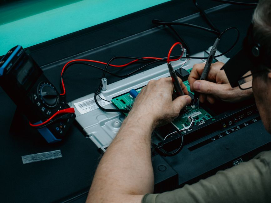
The first test is to measure the adapter’s voltage output to verify it matches the rated specification. Set your multimeter to the DC voltage setting, choosing a range that is higher than the expected output. For example, if the adapter is rated for 12V, set the multimeter to the 20V range. Plug the adapter into a wall outlet, but do not connect it to any device. Identify the output connector on the adapter, which may be a barrel jack, USB port, or proprietary plug. Insert the multimeter’s black probe into the negative terminal (usually the outer sleeve of a barrel jack) and the red probe into the positive terminal (usually the inner pin). Ensure the probes make good contact without shorting across terminals.
Observe the reading on the multimeter display. A functioning adapter should output a voltage close to its rating, typically within 5% tolerance. If the reading is significantly lower or zero, the adapter may be faulty. However, note that some adapters require a load to output full voltage; in such cases, you may need to connect a suitable load, such as a resistor, while measuring. If the voltage is within range, the adapter’s basic power supply is likely working, but this does not guarantee it can deliver sufficient current under load. Further testing may be needed to assess performance under real conditions.
Record the voltage reading for reference. If the voltage is unstable or fluctuating, it could indicate a problem with the adapter’s internal components, such as a failing capacitor or voltage regulator. In some cases, the adapter may output the correct voltage but still fail to power a device due to insufficient current capacity or noise on the output. To check current capacity, you would need to measure the current draw with a load, but this requires a multimeter with a current measurement function and a suitable load resistor. Always ensure your multimeter is rated for the current you intend to measure to avoid damage.
Checking Continuity and Identifying Faulty Components
After verifying voltage output, the next step is to check continuity in the adapter’s circuitry, particularly if the adapter is not working or if you suspect internal damage. Continuity testing helps identify broken wires, blown fuses, or faulty connections. Disconnect the adapter from power and ensure it is fully discharged. Set your multimeter to the continuity or resistance mode. Touch the probes together to verify the multimeter beeps or shows near-zero resistance, indicating it is working. Then, test the adapter’s output cable for continuity from the connector to the circuit board. If there is no continuity, the cable may be broken and require replacement.
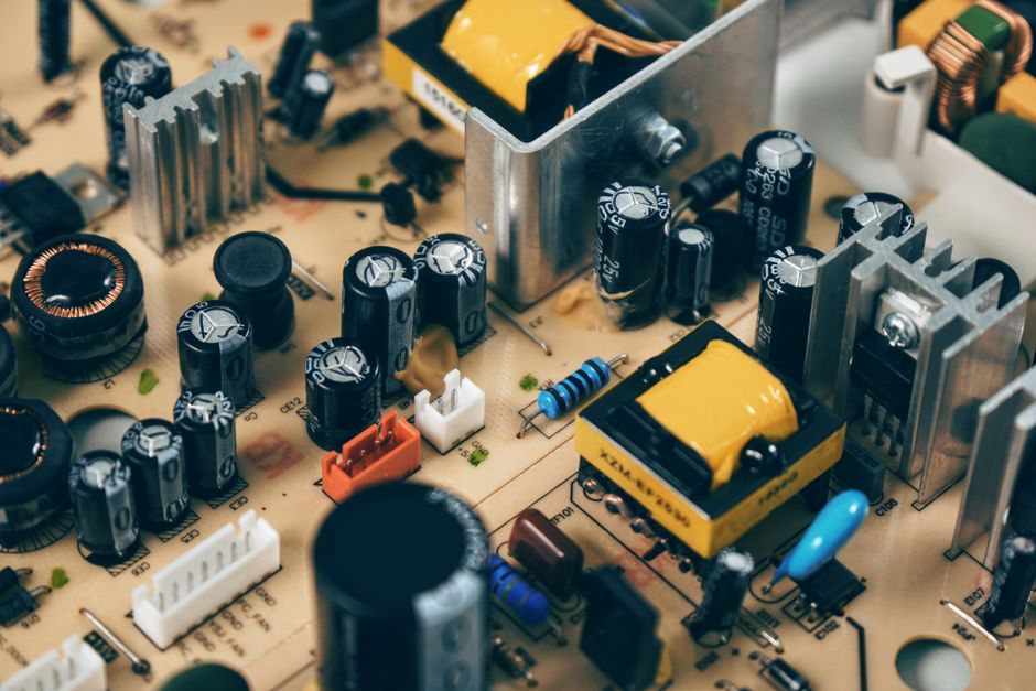
To identify faulty capacitors, you will need to open the adapter casing and visually inspect the circuit board. Capacitors are cylindrical components that may bulge, leak, or show discoloration when they fail. Use a magnifying glass to examine them closely. If a capacitor appears damaged, it is likely faulty and should be replaced. However, note that visual inspection alone is not always conclusive; some capacitors fail without visible signs. In such cases, an ESR (equivalent series resistance) meter or capacitance meter can provide more accurate assessment. FixCircuit suggests that replacing capacitors requires soldering skills and should be done with caution, as incorrect replacement can damage the adapter further.
Continuity testing can also be used to check fuses, inductors, and other components. A blown fuse will show no continuity and must be replaced with one of the same rating. When testing components, always ensure the adapter is unplugged and capacitors are discharged to avoid electric shock. If you find multiple faulty components, it may be more cost-effective to replace the entire adapter rather than repair it, especially if it is a low-cost model. However, for valuable or hard-to-find adapters, repair may be a viable option.
Replacing Faulty Capacitors Safely
If you have identified a faulty capacitor, replacing it can restore the adapter’s functionality. Begin by noting the capacitor’s specifications, including capacitance (measured in microfarads, µF) and voltage rating (measured in volts, V). These are usually printed on the capacitor’s casing. Purchase a replacement capacitor with the same or higher voltage rating and the same capacitance. Using a capacitor with a higher voltage rating is generally safe, but capacitance should match closely. Ensure the replacement is of good quality and suitable for the application, such as low-ESR types for power supplies.
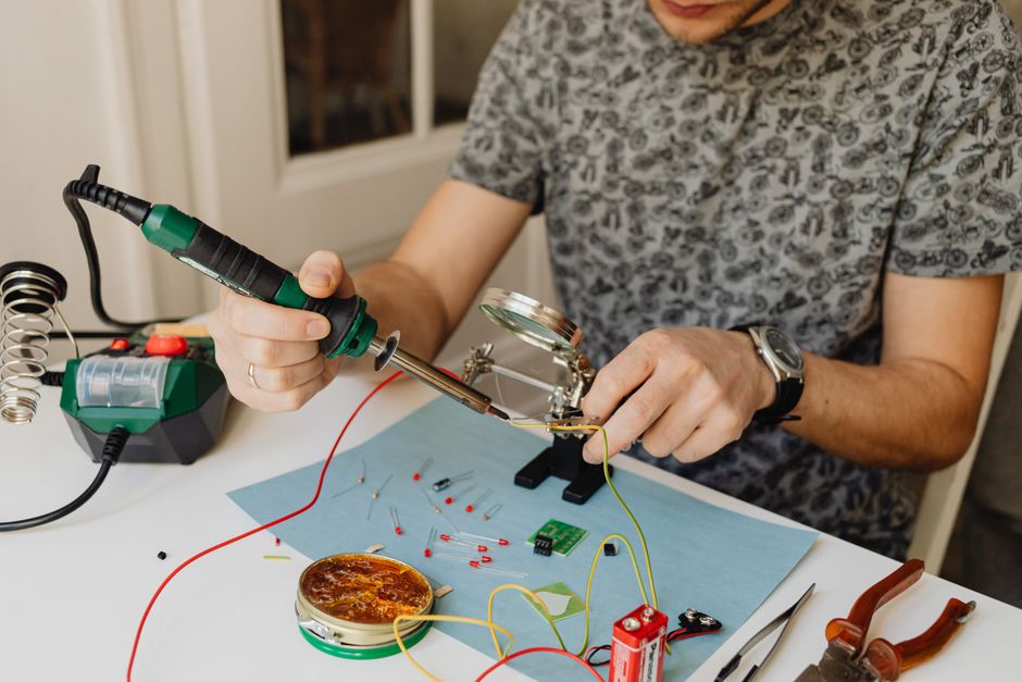
To remove the faulty capacitor, use a soldering iron to heat the solder joints on the underside of the circuit board while gently pulling the capacitor from the top. You may need to use a desoldering pump or wick to remove excess solder. Be careful not to damage the circuit board traces or nearby components. Once removed, clean the area and insert the new capacitor, observing polarity: the longer lead is positive, and the side with a stripe is negative. Solder the leads in place and trim any excess wire. Double-check your work for solder bridges or cold joints before reassembling the adapter.
After replacement, test the adapter again for voltage output and continuity to ensure the repair was successful. If the adapter still does not work, there may be other issues, such as a faulty transformer or control IC. In such cases, further diagnosis or professional repair may be needed. Always remember that working with electrical devices carries risks, and if you are not confident in your abilities, seek help from a qualified technician. FixCircuit emphasizes that safety should never be compromised, and proper tools and knowledge are essential for any repair attempt.